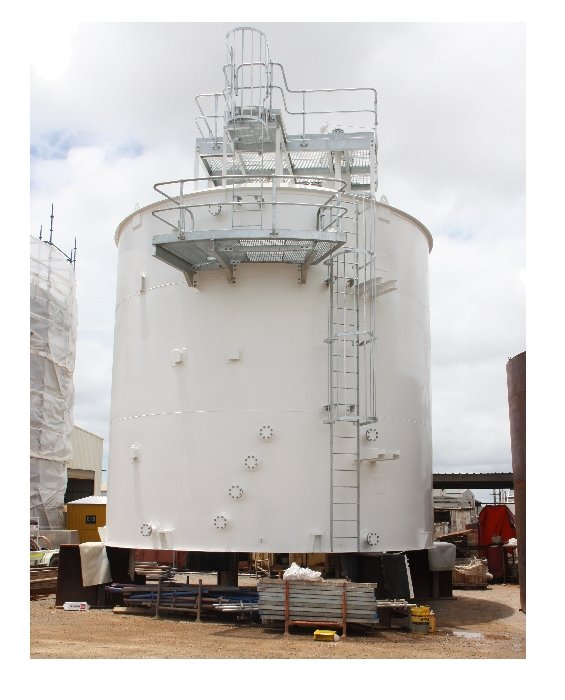
The allowable nozzle load on a tank is a common request; however, the procedure to arrive at an appropriate set of loads is not always straightforward.
Firstly, the allowable nozzle loads on a tank are generally significantly different to a similar sized pressure vessel with a nozzle of the same diameter. In summary, the 40D/60D rule rarely holds. This is primarily due to the vastly different diameter to thickness ratio that exists in tanks. The internal pressure of tanks should not exceed 50kPa (this is a trip point for design to pressure vessel standards) and hence diameter to thickness ratios are generally greater than 600. This ratio is beyond the scale of most WRC 107/297 charts, which is a preliminary indicator that the result will be substantially different to pressure vessels.
Secondly, the increased diameter to thickness ratio implies a more compliant nozzle. The result is less resistance to piping expansion loads and hence a smaller reaction at the connection with the tank. It follows that the piping analysis should consider the stiffness of the tank to calculate a realistic load at the connection with the tank. Therefore, the design of the nozzle connection should ideally be an iterative process between the tank and piping designers.
In reality, it is not always possible for the quick transfer of information between tank and piping designers to occur. In this circumstance, the tank designer must make an estimate of the allowable nozzle loads based on an initial nozzle geometry, generally selected according to experience. The trial loads are selected according to the 30D/40D principle but scaled down according to the tank geometry. The stresses in the nozzle and shell can be evaluated using finite element modelling and compared against pressure vessel codes such as ASME Section VIII, Div 2 or AS1210. The assumption is that the pressure vessel code provides equal, if not greater, protection against failure. Once these initial loads have been established, the iterative process with the piping designer begins, where the nozzle geometry is updated according to whether the allowable nozzle loads are greater than the expected loads calculated by the piping designer.
FEC has extensive in-house experience in the evaluation of external nozzle loads on both tanks and pressure vessels and can assist clients in either application. FEC utilises Nozzlepro software to calculate stresses in the nozzle neck and shell under external loads and the in-built checks against pressure vessel codes to efficiently evaluate the capacity of any nozzle. Where the nozzle is outside the scope of Nozzlepro, FEC have utilised other finite element software such as Abaqus and Strand7 to complete the analysis on first principles to the relevant design standard.
